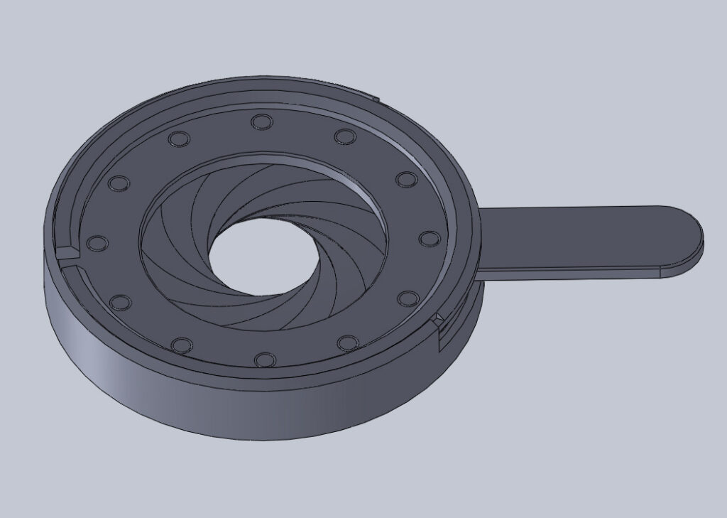
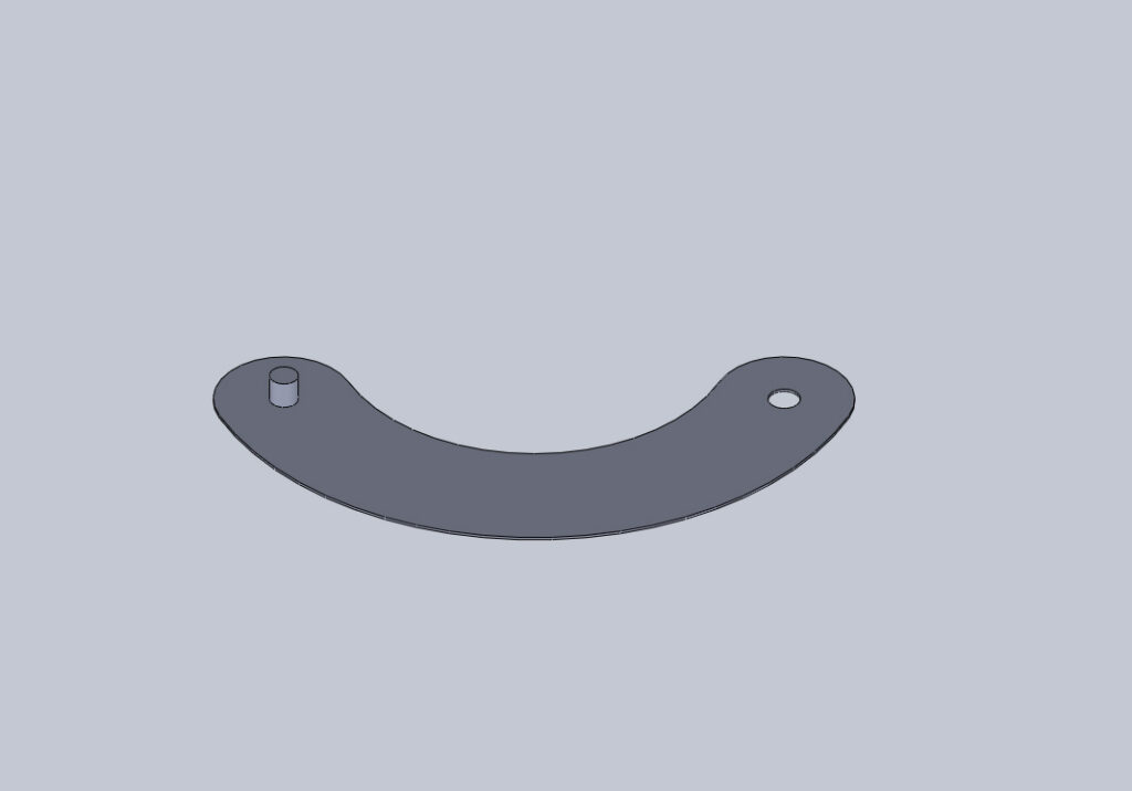
Designing an iris to be easily manufactured is obviously advantageous. One particular challenge is making the leaves with pins on opposite sides, and is a common limitation associated with 3D printing on a FDM printer (also known as FFF). This is because parts generally benefit from being printed flat (see my previous article).
With these printers being almost ubiquitous now, a question that frequently crops up is:
Why can’t one of the pins be printed on the drive ring, instead of both on the leaves?
It’s a valid question, and it makes perfect sense to explore why this won’t really work in the way you think it might.
A ‘regular’ iris layout
All the leaves need a pivot point to rotate themselves so they can sweep across the aperture. Typically this is a pin on the leaf, that sits in a hole in the drive ring. The leaves can then all be stacked around the drive ring in their parked position, and traverse the aperture in unison when the iris is operated.
The ‘alternate’ layout
Lets now switch these around, so that the hole is in the leaf, and the pin is on the drive ring.
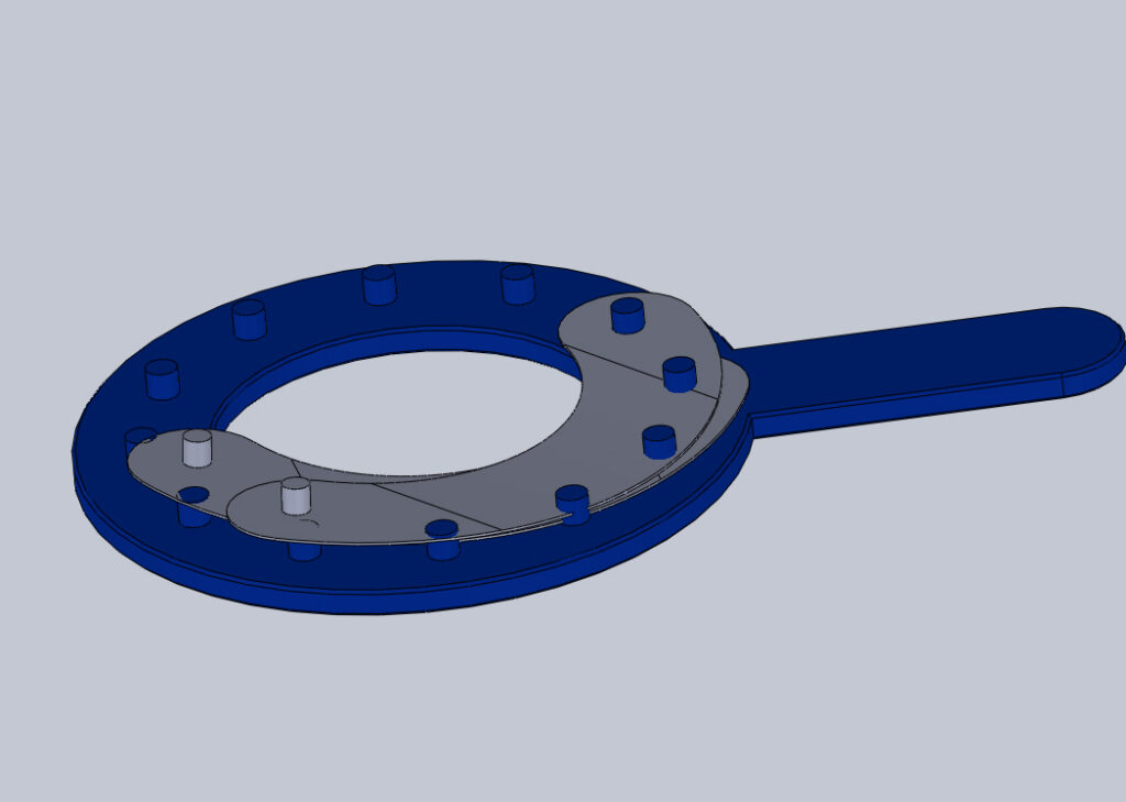
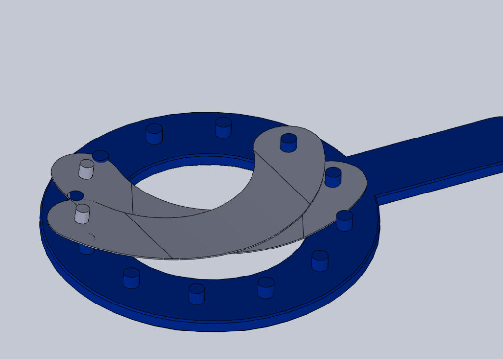
To keep things visually simple in our example iris, I’m only going to be showing 2 of the 12 leaves (grey) attached to the drive ring (blue). The slots the pins of the leaves slide in are hidden (along with the body itself).
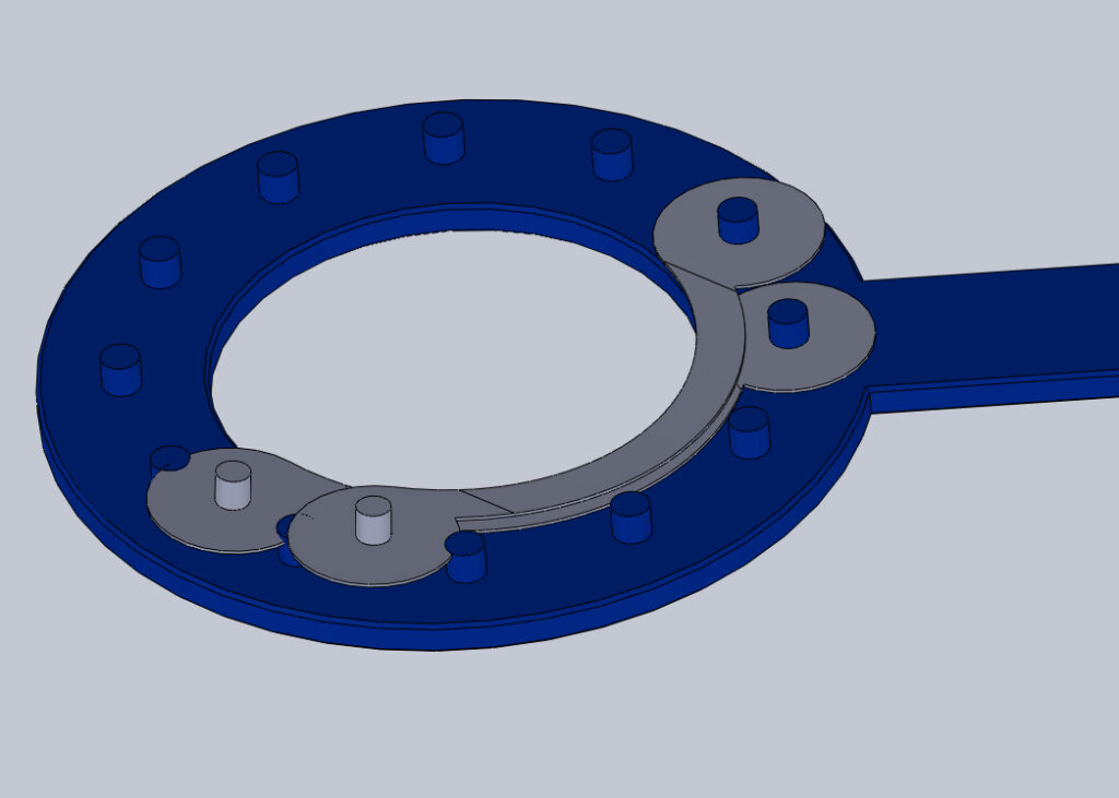
As you can see below, we immediately have a problem. The drive ring pins are protruding through the leaves when they’re sat, stacked in their parked position. Even closing the aperture slightly, the pins still interfere with the leaves.
OK, no problem. We’ll be clever, and cut a little slot out of each leaf to allow the pins to pass through. But, wait… That’s not going to work either, because we’d need multiple slots cut in each leaf, compromising our coverage of the aperture with holes. Effectively we’d be thinning the width of the leaves, and in doing so restrict our aperture coverage due to the limited overlapping of the leaf material.
Working the problem
You could possibly make the idea work by keeping the iris closed down, and limiting how far the leaves can pivot open. This would prevent their back-edges from interfering with all the pins – but at the expense of having an incredibly narrow aperture range. And even still, at the slot end, the pins would interfere with the leaves, so yet another compromise would again need to be made.
Additionally – if we forget about the leaves for a moment – a major issue currently hidden out of sight, is that the drive ring pins are trying to hack their way through the bodies slots, as the drive ring rotates. Actually, in reality, the leaf’s pinned ends would be sitting atop the drive rings pins, meaning extra height in the body’s cavity space would be needed. I suspect that the leaf ends would catch and snag on the drive ring pins regardless though.
Perhaps if the drive ring pins were really really short, and their tops were domed slightly to allow the leaves to easily slide over one-another, that could possibly work. The domed tops would likely have to retain the leaves in place, otherwise the leaves would come off short pins far too easily. However, it’s not really ideal to have material between each leaf, as this both creates separation gaps between the layers and foreshortens the leaf’s span – which is what would happen with each dome lifting it’s neighbours leaf that rests on it.
In conclusion, it’s probably best to just put both the pins on the leaves…
If you’d like to have a go at making your own iris design, please do sign up to our design software. You’ll be able to customise the size and many other design parameters. And once you’re done, you can export and print the templates as a guide.
