Papercraft is a wonderfully accessible thing, and so what better project to make than a paper iris diaphragm. Building on lessons learnt from last time, we go into more depth, and cover every single step in the design process.
What Is An Iris Diaphragm?
Let’s start with a quick recap and inform ourselves what an iris diaphragm is, what an iris diaphragm does, and what an iris diaphragm can be used for:
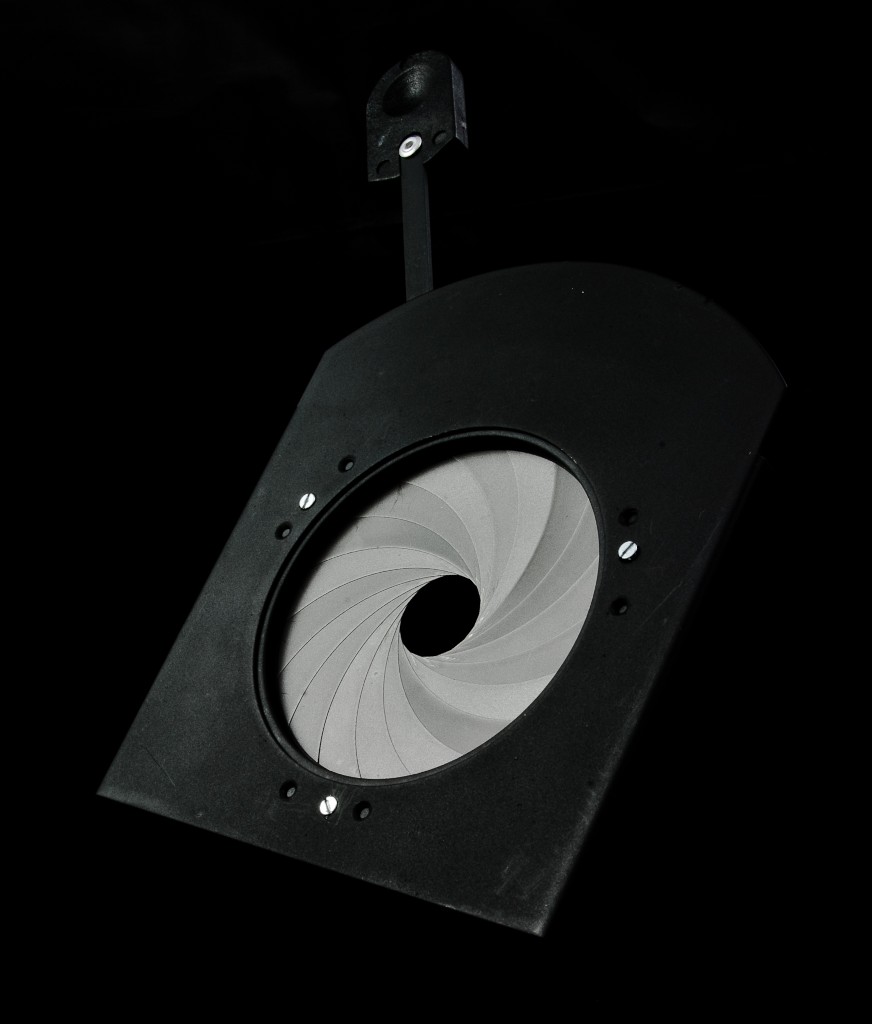
An iris diaphragm is a mechanical device, consisting of a circular array of leaves that move in unison, together forming a variable aperture. They’re designed to manage the flow of photons or particles, by blocking out any excess, and allowing only a controlled amount through. Famously they’re used in cameras, but they also offer a wide-variety uses in many different industries, such as theatrical lighting, fibre-optic manufacturing, HVAC, picking & handling, and many more.
Tools Needed For Making a Paper Iris
- Scissors, or a craft knife
- PVA glue and a small applicator (brush, cocktail stick, etc.)
- Scotch tape (or equivalent).
- Printer paper to print the template on (about 5 pages, the heavier/thicker the better)
Planning Your Iris Design
Materials, tools, and construction
We’ve already begun setting some of the boundaries of our iris design. We know we’ll be using printer paper, and to cut the parts out we’ll be using scissors or a craft knife. So that means our iris can’t be bigger than Letter (or A4) paper, and ideally it needs to not use too many leaves in it’s design - so we don’t have a soul-destroying amount of parts to manually cut out.
Design purpose
Next it’s likely we’ll have some idea of a use, or a purpose, for our iris. For example it could be for a circle maker, the eyes of a character, or a circular measuring device. Or it could just be for the fun of it - and that’s a perfectly good purpose too. Obviously, being paper, it may not be a good idea to use it where it could become wet, or be a fire hazard.
Ergonomics
Will it be a good size to easily operate in your hand? Will it be easy for someone else to operate?...
Manufacturability
It’s all very well designing an amazing iris, but if it’s near impossible to make then we’ll be needing to go right back to the drawing board. So we should consider whether our parts will be big enough to easily cut out, and also big enough to assemble easily.
Moving parts
Some things to keep in mind are that our rotating and sliding paper linkages will need some space consideration. They also sometimes need to borrow material from what is being cut out, so it can be folded back on itself.
How To Design An Iris Diaphragm
 For simplicity we’ll be using the Iris Calculator to help design our iris for us. That way, we can speed up the iris design process significantly, and get straight onto making one. Follow these steps to get yourself setup:
1. Go to https://iris-calculator.com/plans/iris-design-packages
2. Create a new account.
I’d recommend you choose ‘Monthly’ as it will design what you need, and then you can cancel your account before the month is up (should you wish). But you also have 3 options to chose from: ‘Free’ will give you a feel for what it can do (but you won’t be able to export your design, and you’ll be limited in what size of iris you can design). ‘Monthly, and ‘Yearly’ will both give you full, unrestricted functionality for the duration of their respective periods.
3. Now that you have an account, and are logged in. Go to the design page, and you’ll be presented with an initial iris design as a starting point. You can open and close it using the ‘O’ key on your keyboard, or clicking the ‘Open/Close’ button on-screen. Below the iris drawing, you have the dimension inputs that tell the software what size you want to design.
4. The most important dimensions are the aperture size, and the outside diameter. All the rest can be used to fine-tune your iris design once we get in the ball-park. Feel free to chose your own size and experiment a little.
Now we need to bear in mind that the software assumes we’re using rigid materials to make the iris out of – like brass, or aluminum. And because we’re going to be using paper, we’re going to need to factor in it’s properties – namely it’s tendency to tear, and it’s bendy-ness.
To minimise the chance of ripping, tearing, and bending, we’ll need plenty of margin between cut-out out areas. That includes making the design with space to have the slots with closed ends. We can actually exploit paper’s ease of bending, and use it to our advantage in places, by making folds to help with assembly.
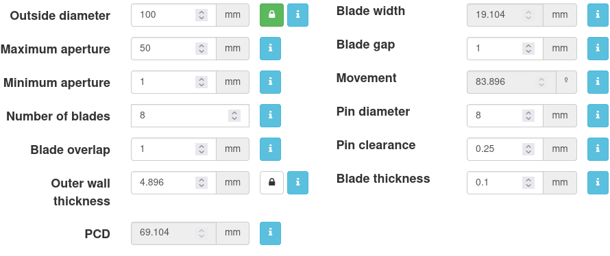
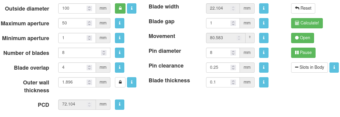
5. Click ‘Reset’ so we’re all starting from the same point. For our example we’ll enter the following dimensions and then click ‘Calculate!’:
Outside diameter: 100 mm - make sure to click the lock button too (the reason we lock it is because we don’t want any of our other dimensions to have an influence on it and change it).
Maximum aperture 50 mm
Minimum aperture of 1 mm
Number of blades 8
Pin diameter 8 mm
6. What you may notice when the iris is designed with these new dimensions and closes, is that the pins slide almost into the aperture of the iris.
To make it a little easier to see what I'm talking about, click the '2' button at the top next to the green 'Blade array' button. This displays only 2 of the blades in the array, and if you open and close the iris (with the 'o' button on your keyboard) you can rock it back and forth at the point the drive pin nears the aperture. Pressing 'P' on the keyboard will pause the motion, to help hold it there.
We spoke about having the slot ends closed - giving extra strength to prevent the slots from deforming during operation. In order to have the space available to do this, we’ll need to move the position of the pin away from the aperture. And the simplest way is to increase the ‘blade overlap’ value.
What we’ll essentially be doing with this control is making the blade wider, and thus will be moving the pin outwards too.
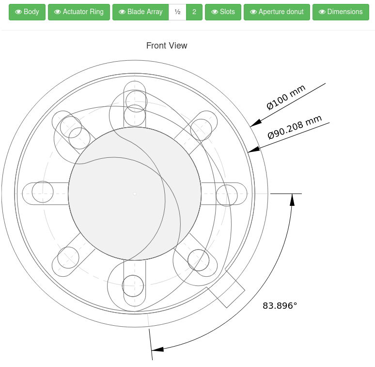
7. Enter 4 mm for the ‘Blade overlap’ and click ‘Calculate!’ again. This should then give us enough space to keep the pin well within the slot, and allow us to close the end without it interfering with the pin as it travels down the slot.
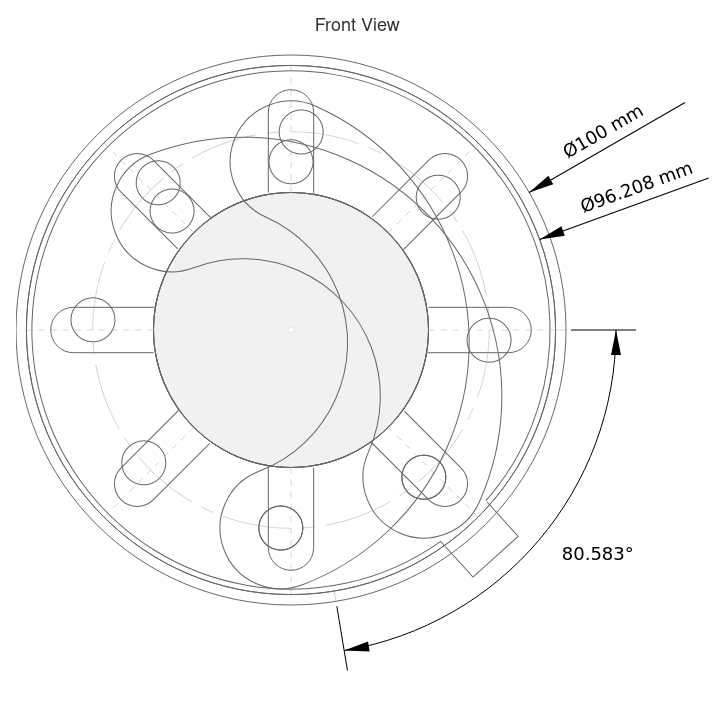
8. And that's our design done! Next we export it...
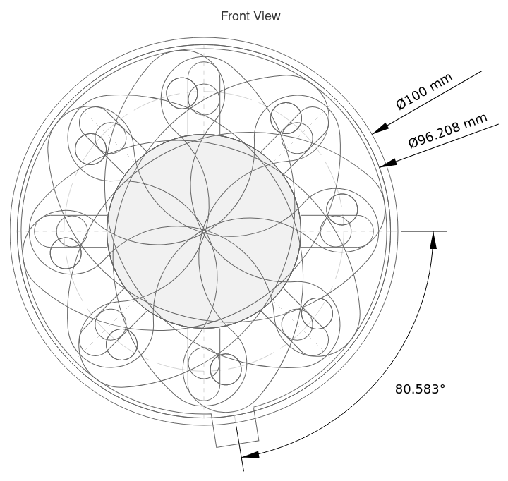
Prepare the iris parts
Now we have our iris designed, the next step is to get all the parts onto paper, and ready to cut out.
We’re going to need to modify our design slightly in CAD to make it work in paper form. Don’t worry though, these are all very simple changes, and should only take a few minutes. What we’ll be doing is the following:
- Make the pins in the blades fold outwards
- Close the ends of the slots
- Add a handle to operate the iris
- Add some flaps to fold and hold the iris all together
- Draw a simple lid/cover
- Draw a pin end cap
To get started, click the ‘Download DXF’ button. This will then download a zip file containing all the parts for our iris in the DXF file format. DXF stands for ‘Drawing eXchange Format’ and is a universal file format for CAD (Computer Aided Design) drawings.
Go ahead and unzip the files to somewhere convenient. The list of files will look something like this:
Actuator_RingXX-XX-XX-XX-XX-XX_X.dxf

Blade_XX-XX-XX-XX-XX-XX_X.dxf

Housing_XX-XX-XX-XX-XX-XX_X.dxf

Iris_Assembly_XX-XX-XX-XX-XX-XX_X.dxf

Iris_Dimensions_XX-XX-XX-XX-XX-XX_X.dxf

Pin_XX-XX-XX-XX-XX-XX_X.dxf

README.txt
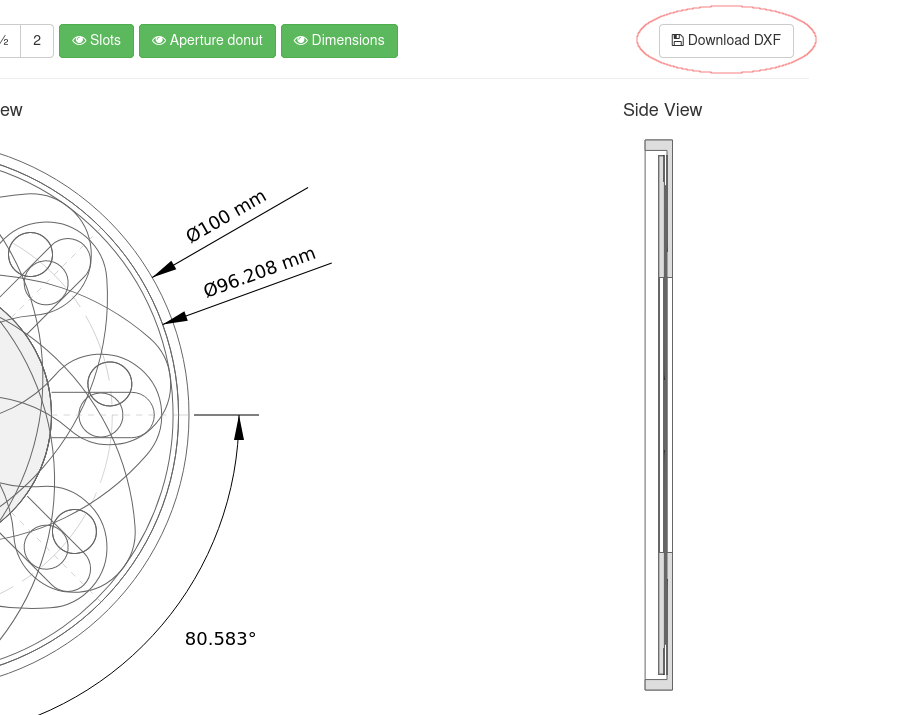
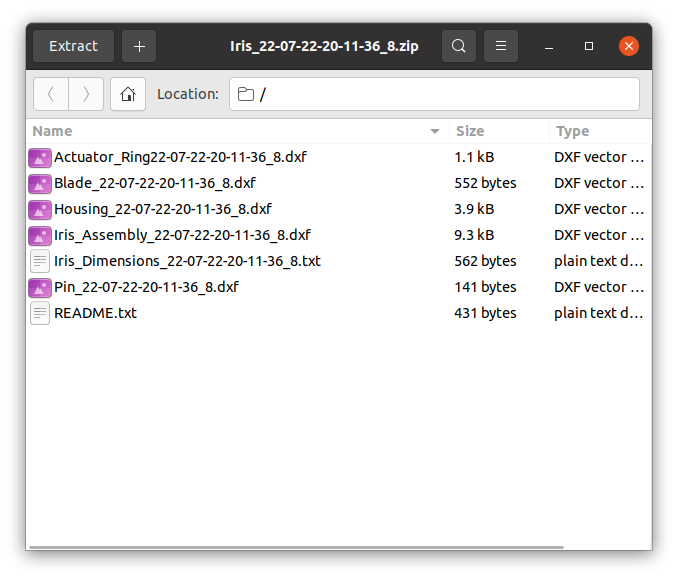
You will need a CAD program to open these files. We’re going to use a program called LibreCAD, which is open source and available to download and use for free. You can download it here: https://librecad.org/
(Of course, if you already have a CAD program, and you’re comfortable using it, then go ahead and open the iris part files in that.)

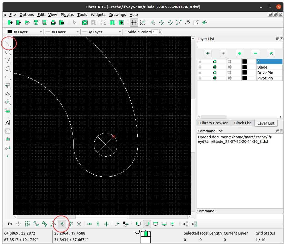
First we’ll open our Blade file in LibreCAD, enable ‘Snap middle’, and with the ‘2-point’ line tool draw 2 lines across each pin. These will be our cut lines to be able to fold open the pin holes. You can use the mouse scroll-wheel to zoom in and out to help see what you’re doing. When done, save it.
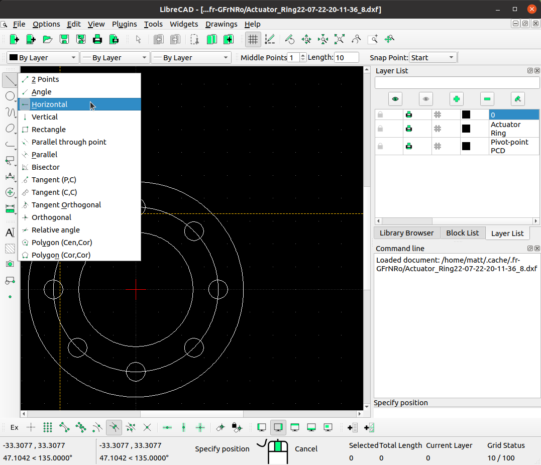
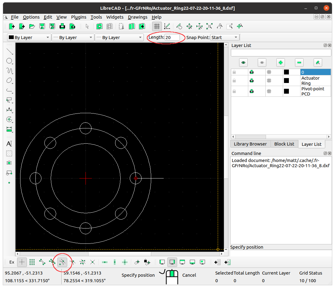
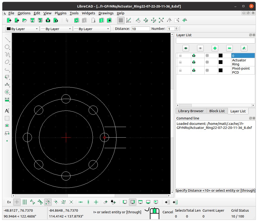
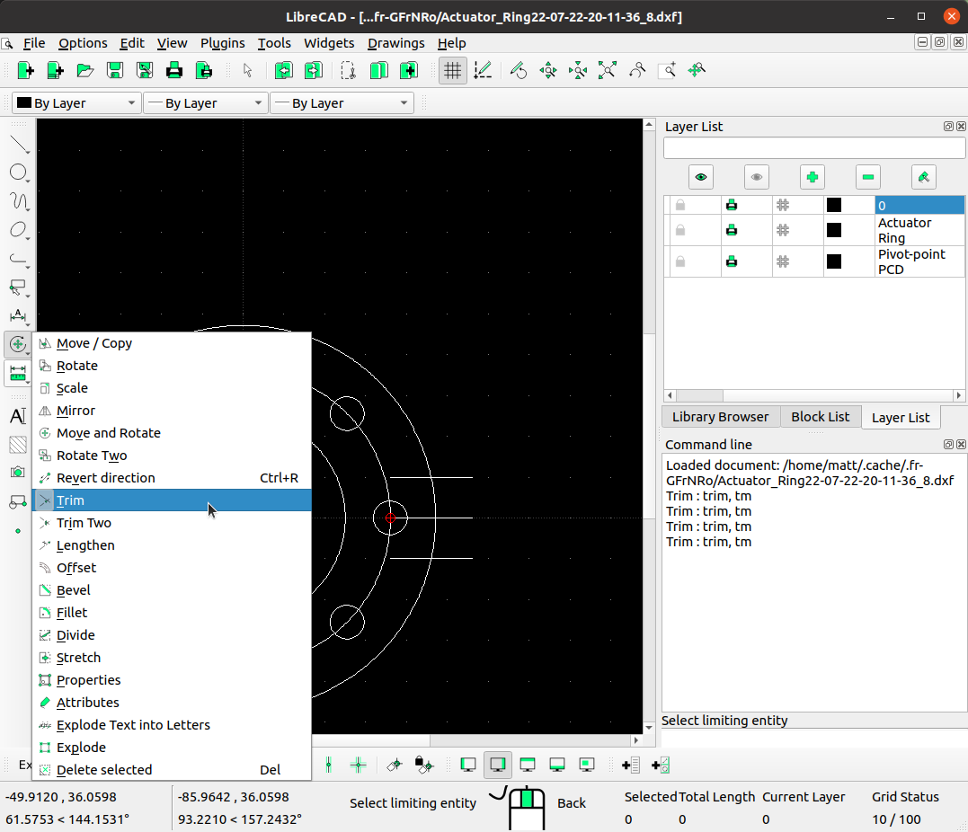
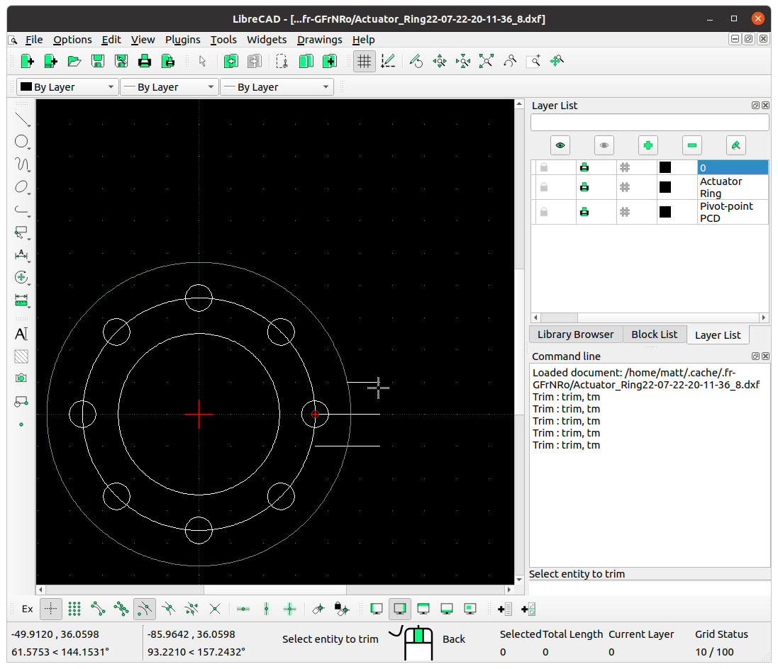
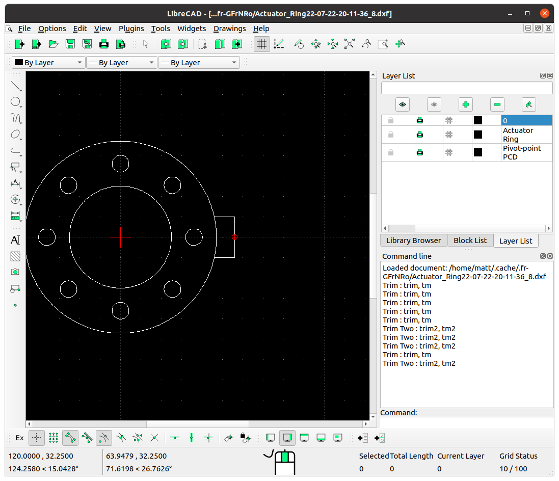
Next we’ll open the Actuator ring file and add a handle. To do this we’ll place a ‘horizontal line’ from the center of the right-most hole, which we’ll set as 20 mm. Then draw a parallel line of 10 mm above and below the width of the handle. And then we can trim the sections of lines that aren’t needed, delete our centre-line, and draw a line on the end. We can also delete the pin-hole PCD (the circle intersecting them all) as we don’t need it. When done, save it.
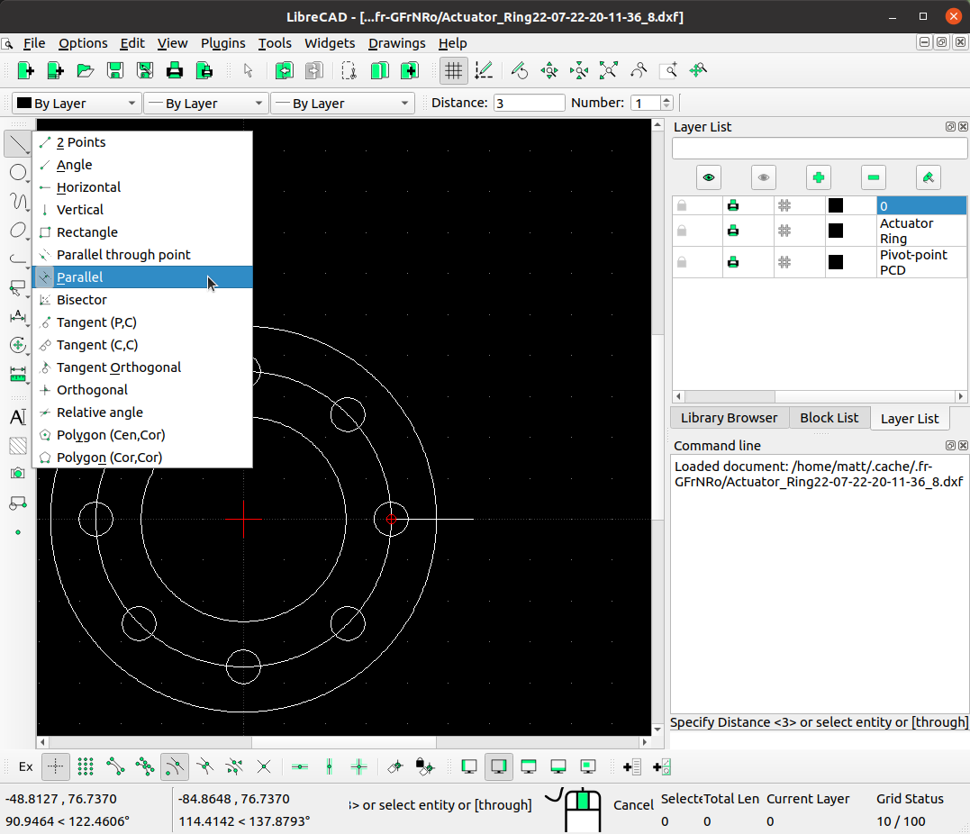
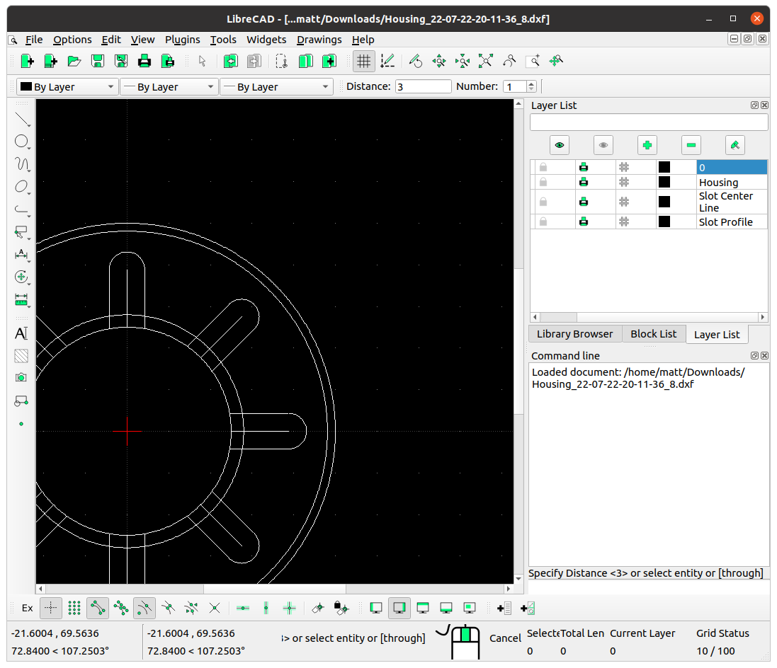
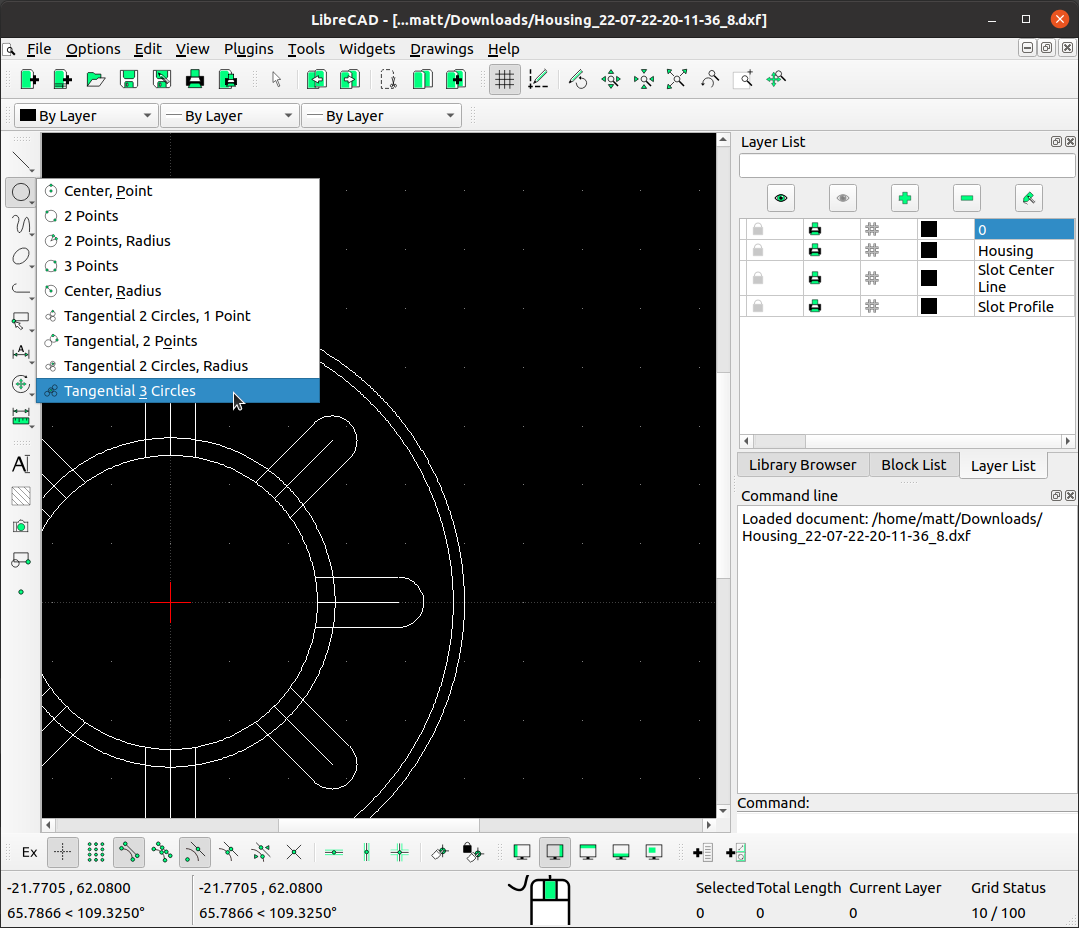
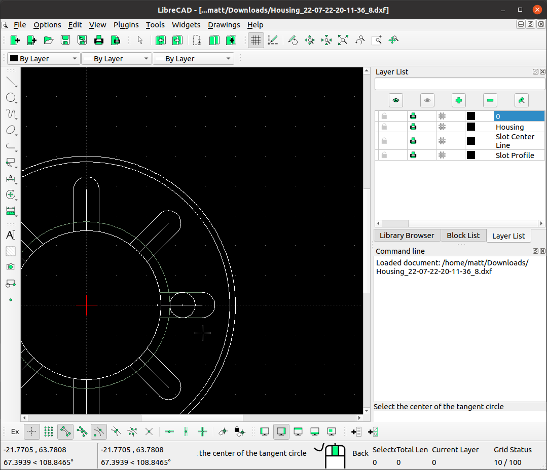
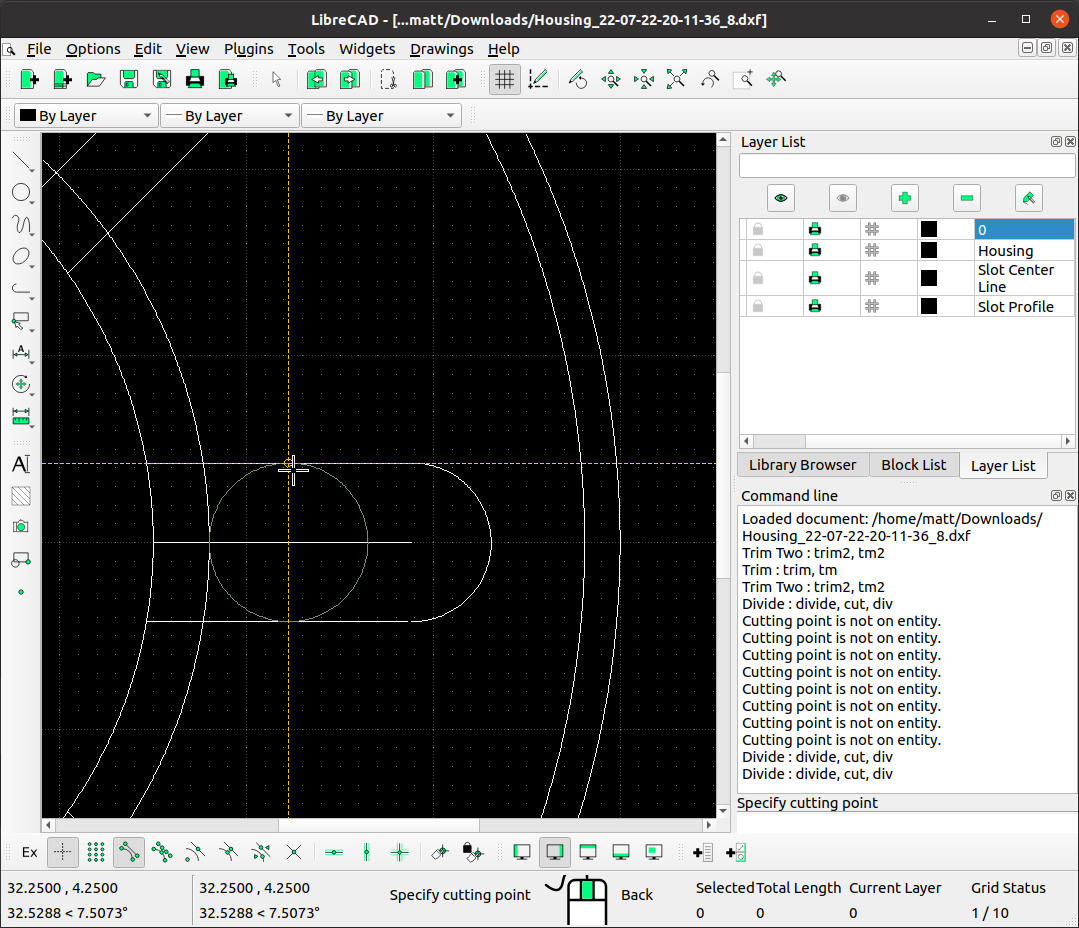
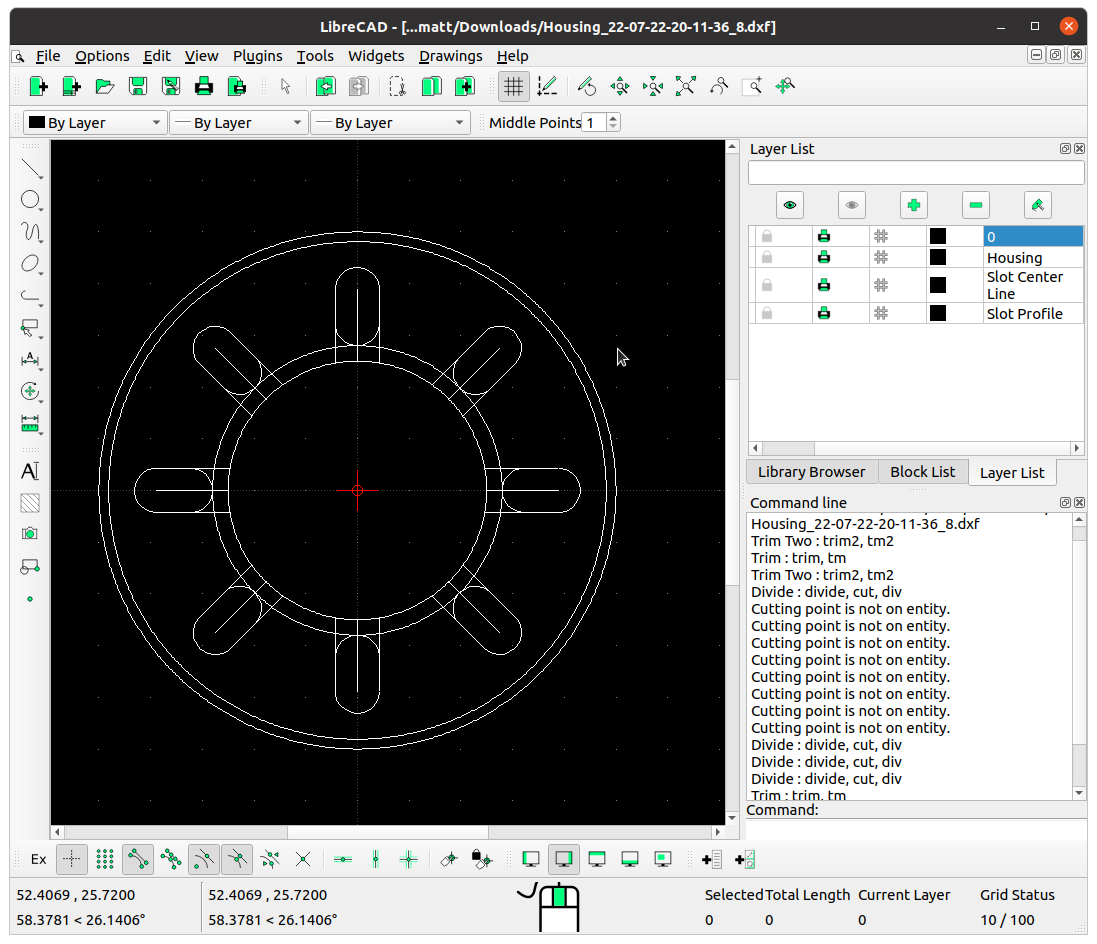
Now we’ll open up the Housing file, and get the ends of the slots closed off. Select 'Parallel' under the line tools, and make the offset distance 1.5 mm. Hover over the maximum aperture circle and create a circle on the outside of this. Then draw a 'Tangential 3 circles" circle using one of the slots parallel lines and the circle we just created.
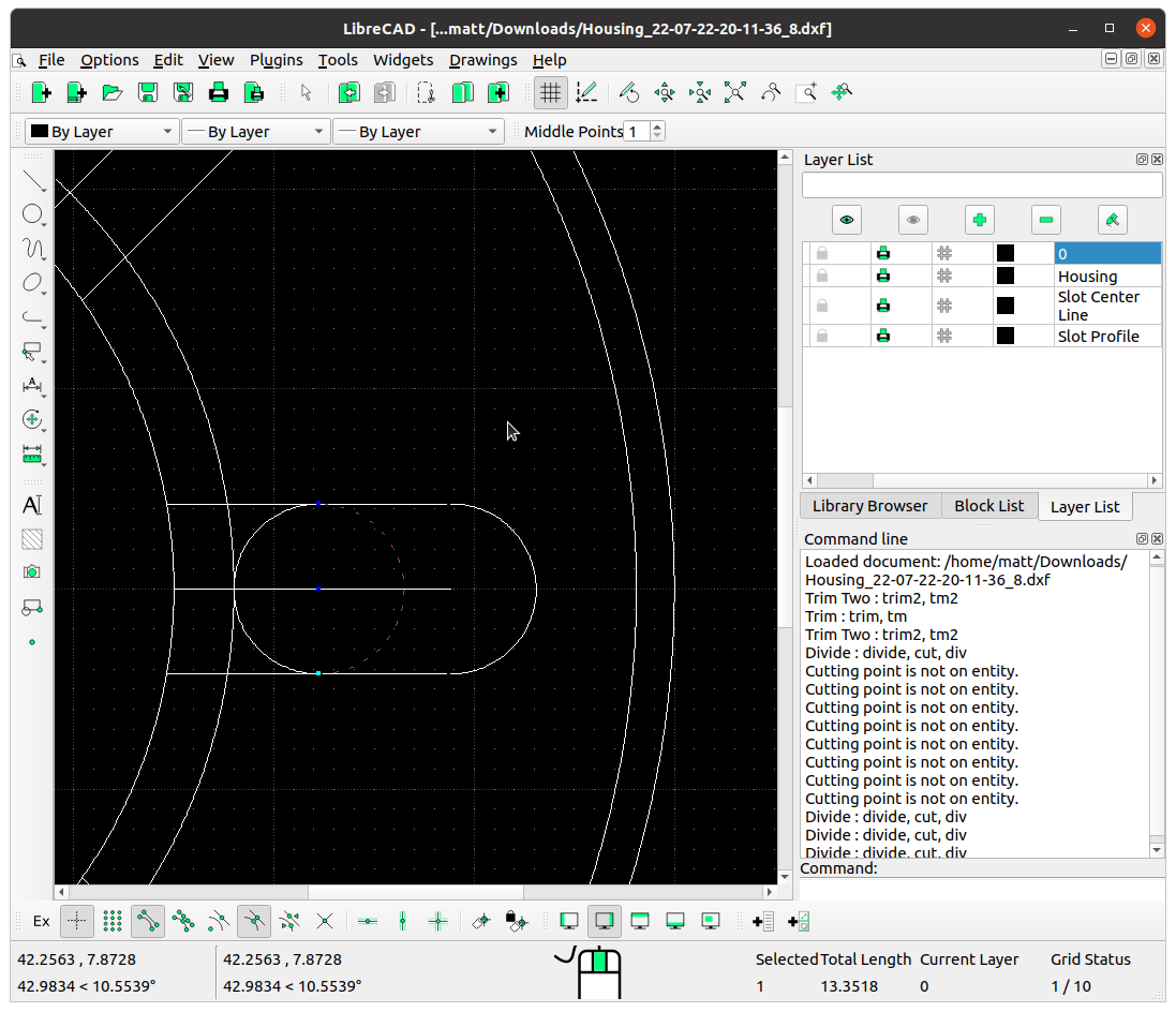
We'll use the 'Divide' tool to trim this circle as the end of our slot. Select the circle, then the top point, and repeat for the bottom point of the circle to divide it up straight down the middle (you may need to use snap middle to help). Then escape out of the tool (Esc. on the keyboard), and left-click the right-hand side of the circle to select it. Press the 'Delete' key to remove it.
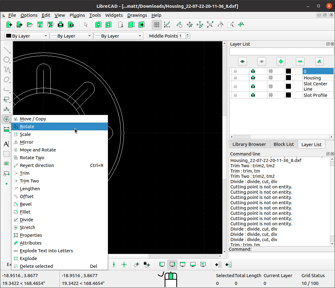
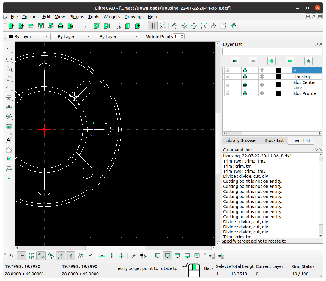
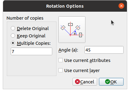
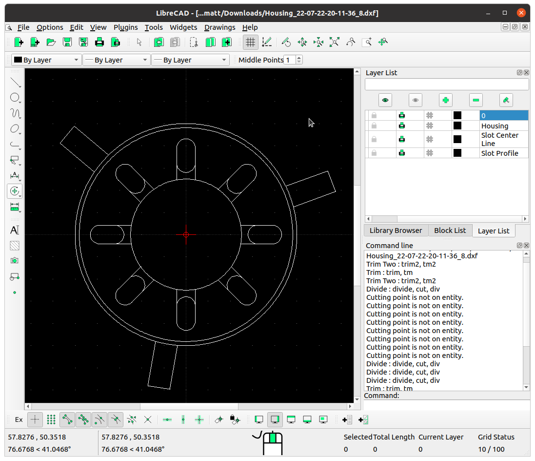
Select the half circle we're left with, and using the 'Rotate' tool, make 7 copies rotating around the centre of the iris.
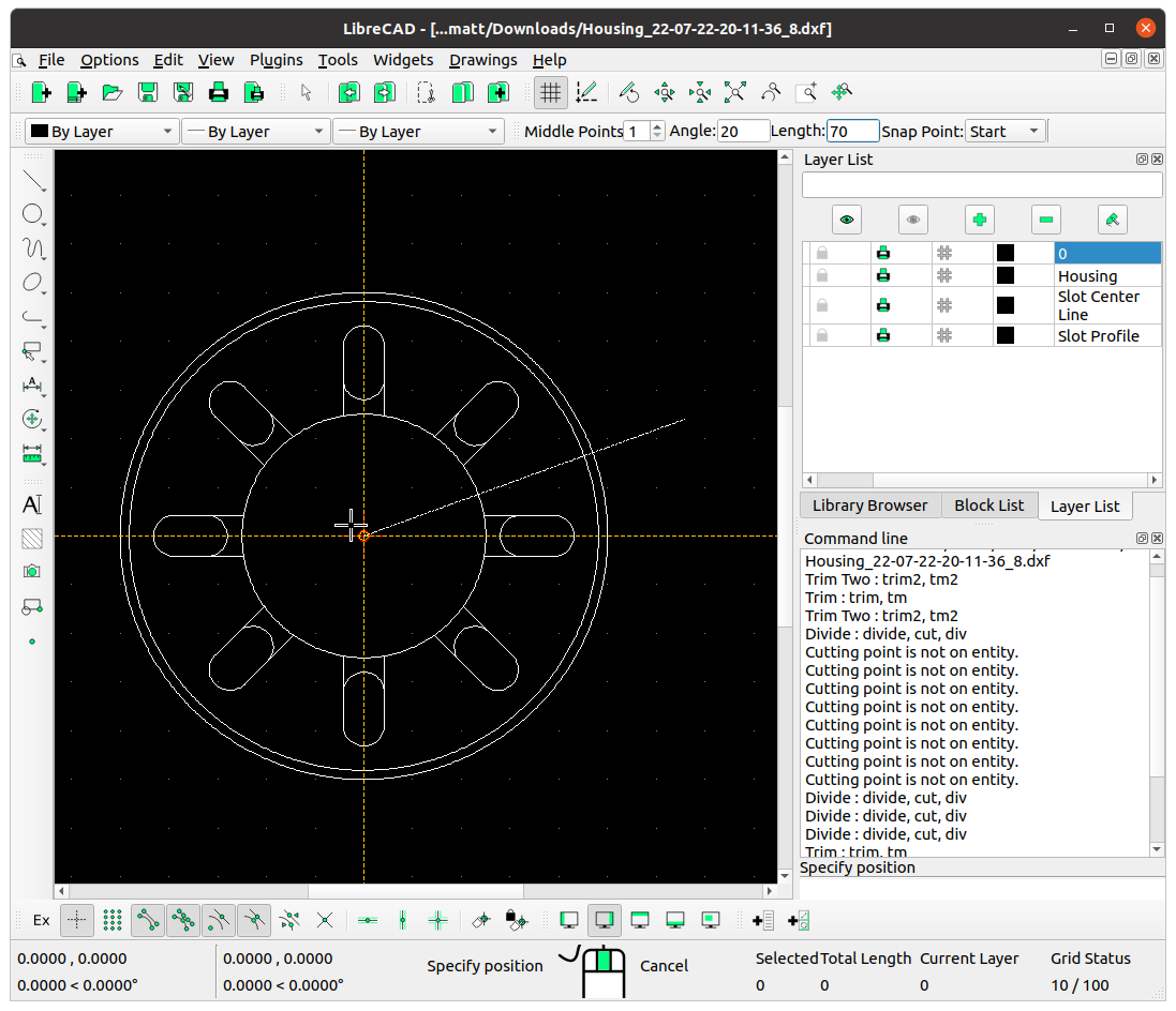
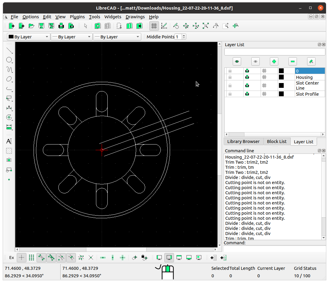
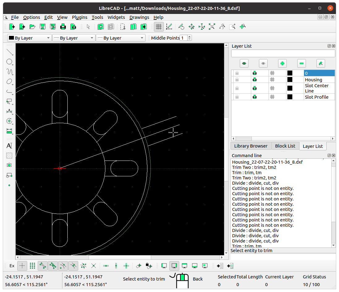
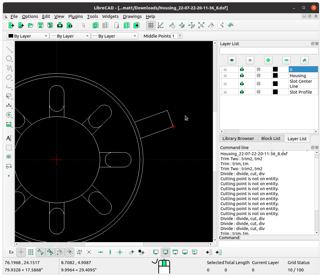
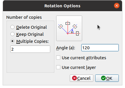
Add some flaps, which will be used to fold over and retain everything in place. Draw an 'Angle' line from the centre at 20 degrees, with a length of 70. Draw a parallel line either side, and then delete the centre line. Trim the 2 lines at the outside circle, and then 'Rotate' 2 copies at 120 degrees.
Again save the file when done.
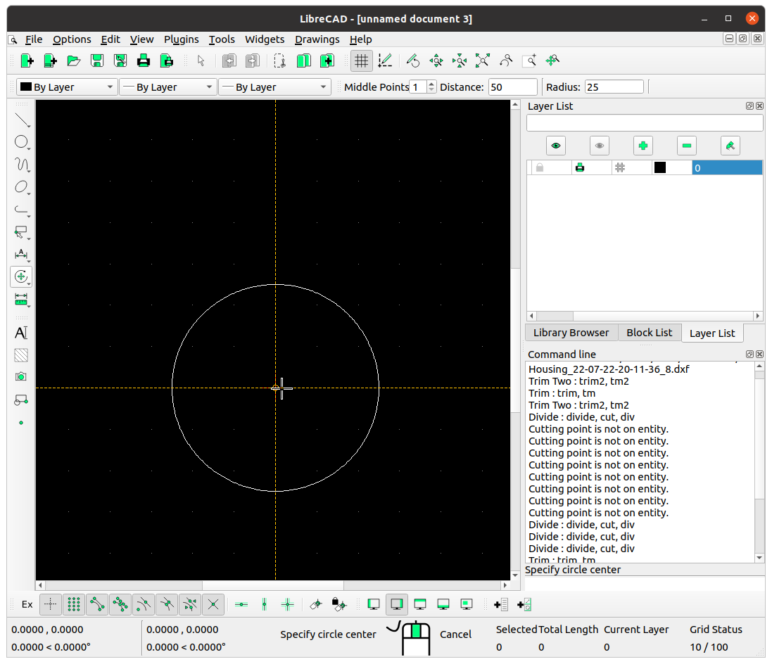
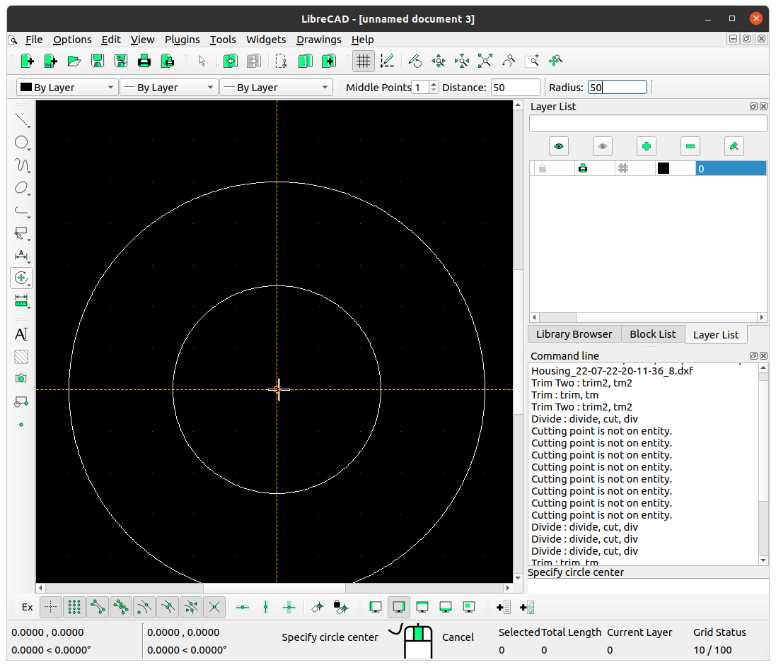
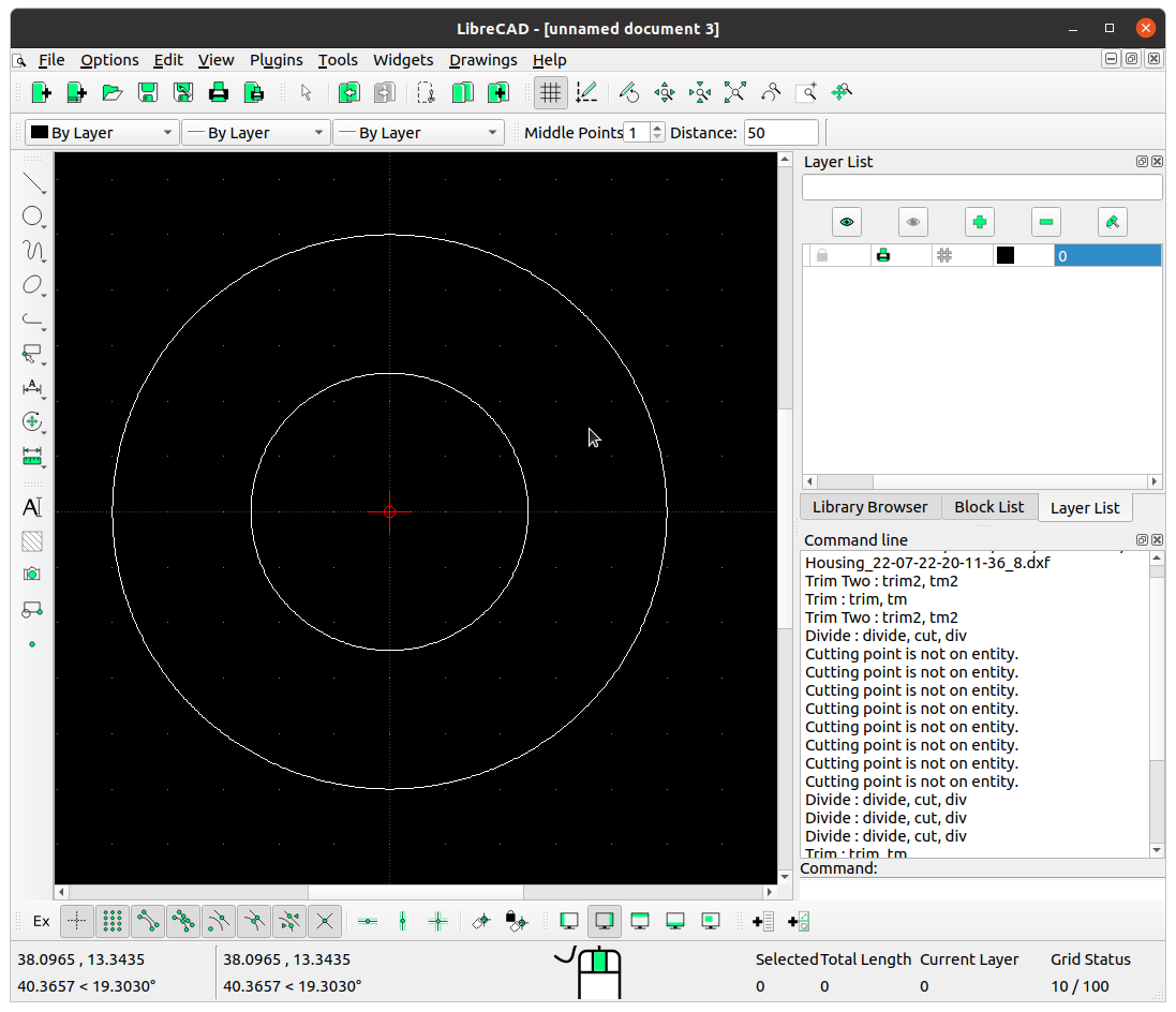
We’ll also be needing a lid or cover for our paper iris. Create a new drawing and draw 2 concentric circles. One with a radius of 25, and another with a radius of 50.
Save this file as ‘Cover’ with the rest.
We'll also do the same for the pin caps. Create a new drawing and draw a circle with a radius of 7.5.
Save this file as 'Pin caps'.
(We can ignore the Pin file that was also downloaded in the set of drawings, as it’s not needed for our paper iris. And the README.txt file is just a reference to the dimensions of our iris).
Print the paper iris parts
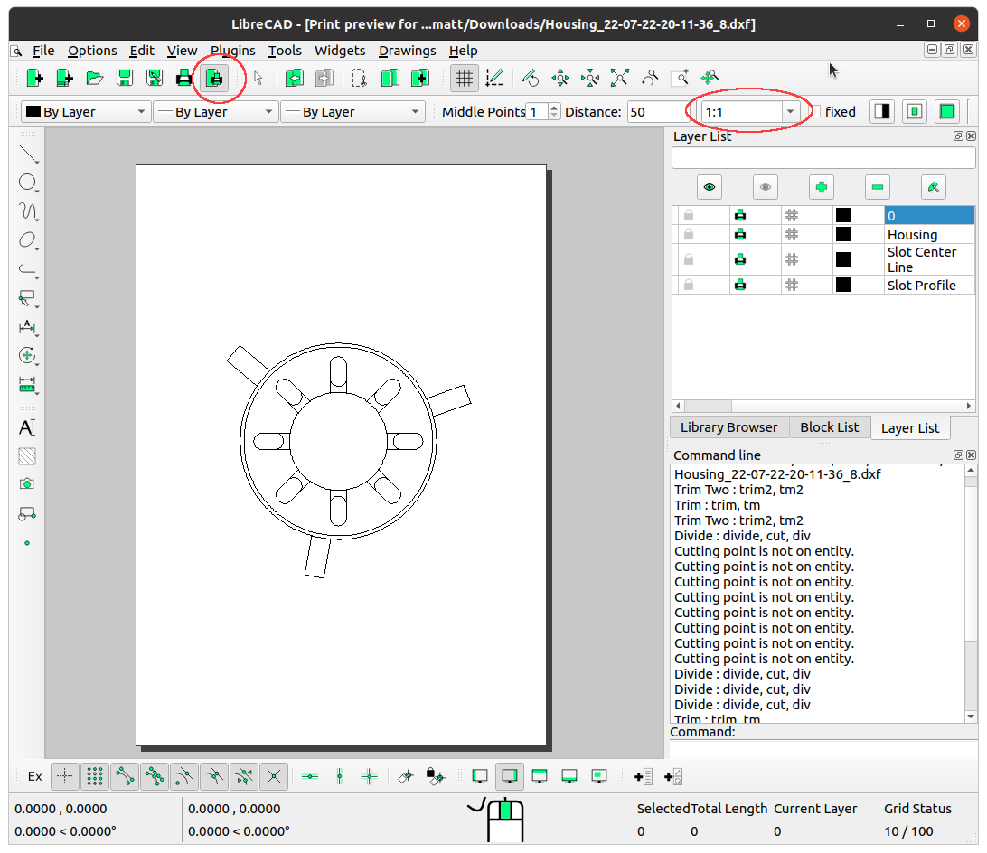
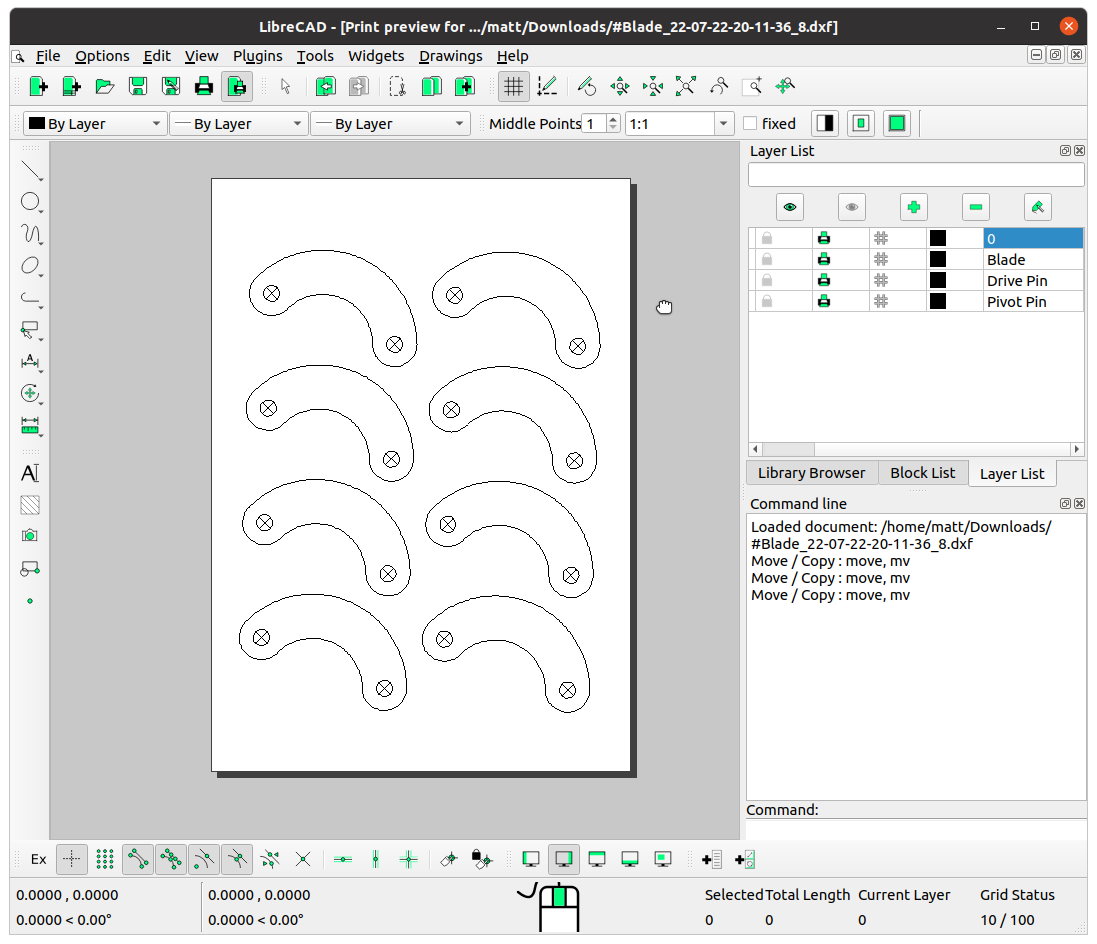
Alright, we’re almost there! Next, we need to print out our parts, and get them cut out. For each part, click the 'Print preview' button and set the scale ratio to '1:1', then print.
You should print 8 blades, 8 pin caps, 1 actuator ring, 1 housing, and 1 cover.
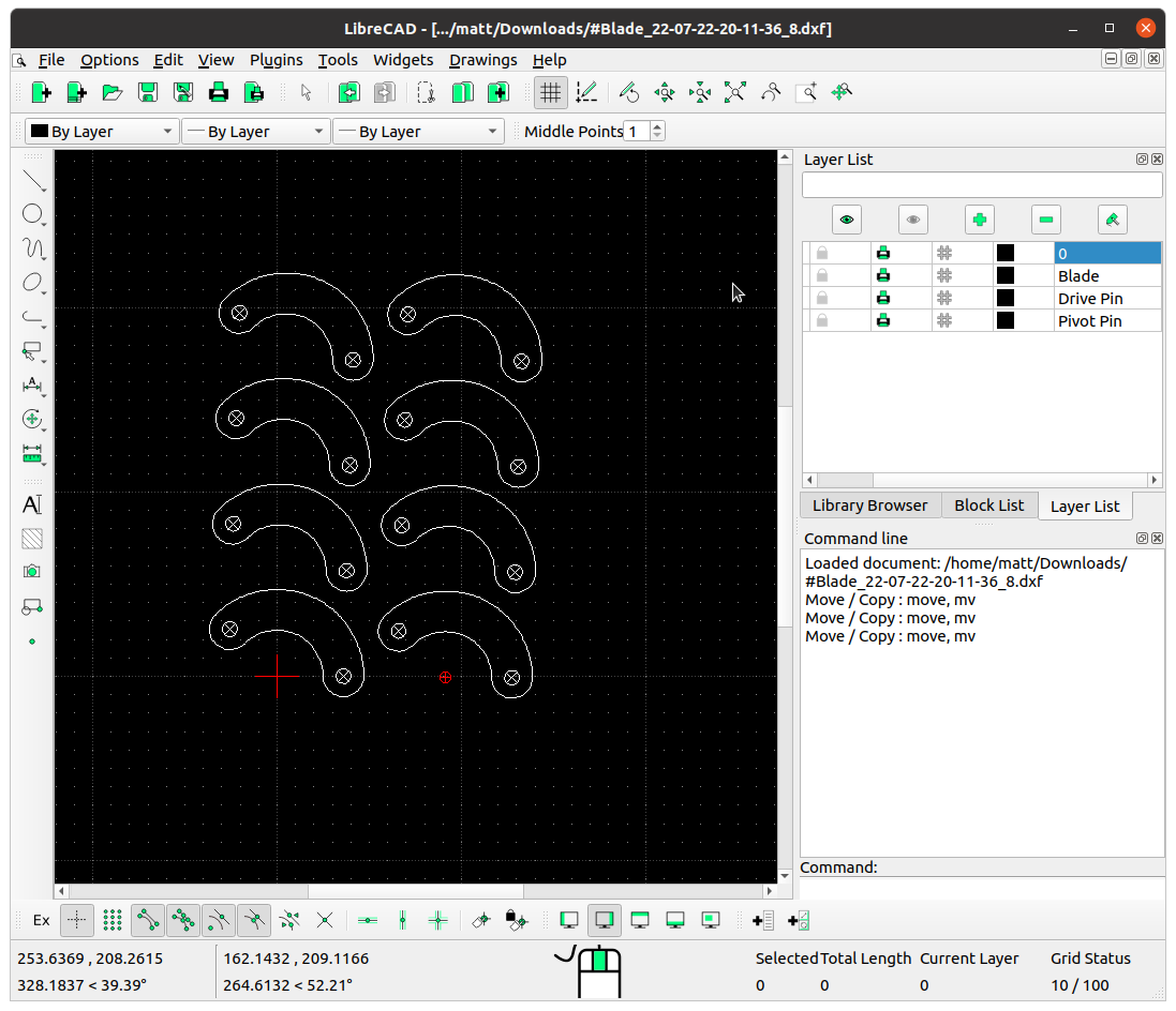
For the blades and pin caps, you might want to save paper by using 'Move / Copy', and having all eight on one page.
Cut out all the parts
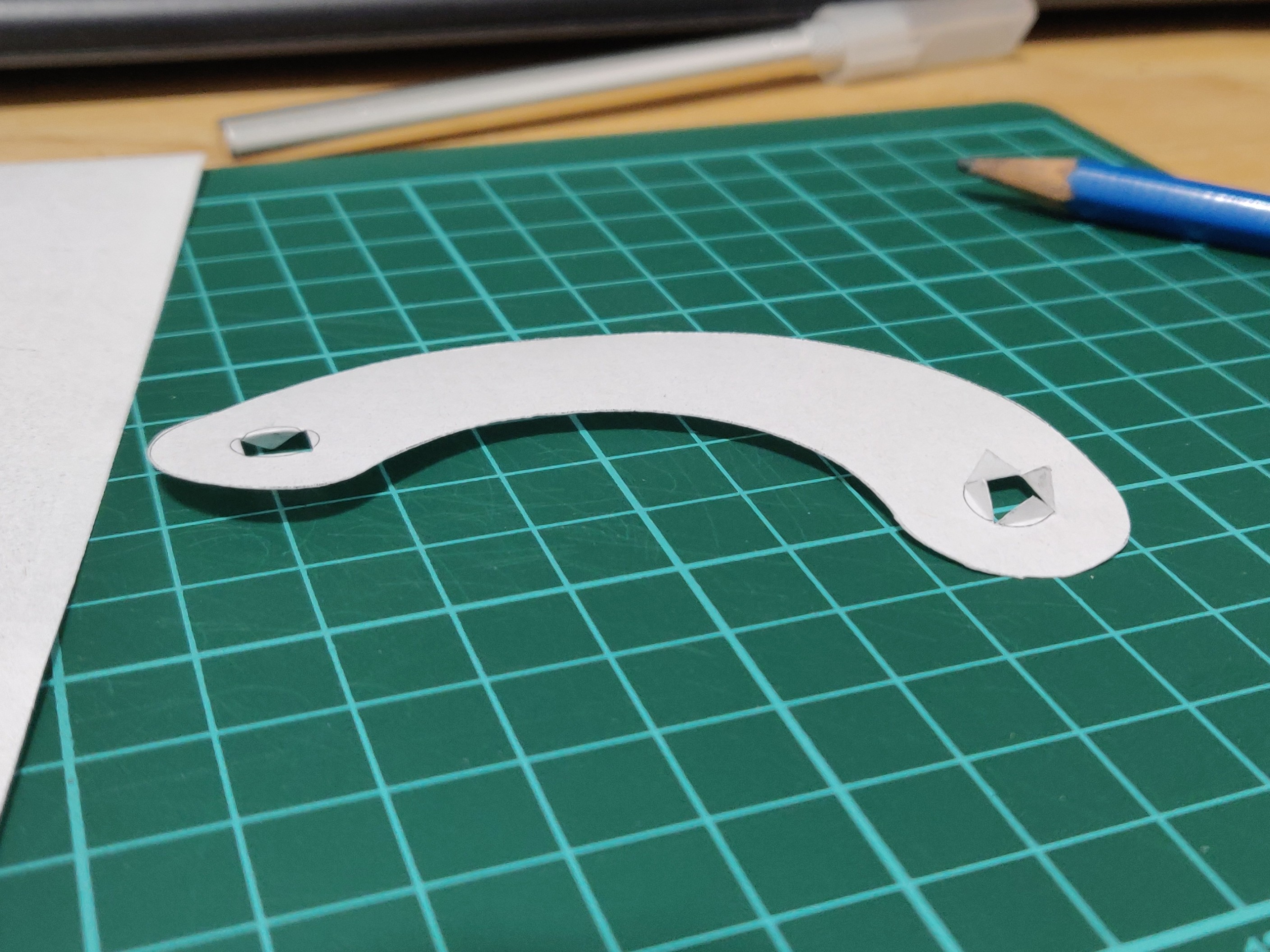
Cut the 2 pin hole lines in the blades exactly. It's important to get them right - if you screw up by cutting them too far beyond the hole it will be too tight when installed, so chuck it, and start again with a new blade.
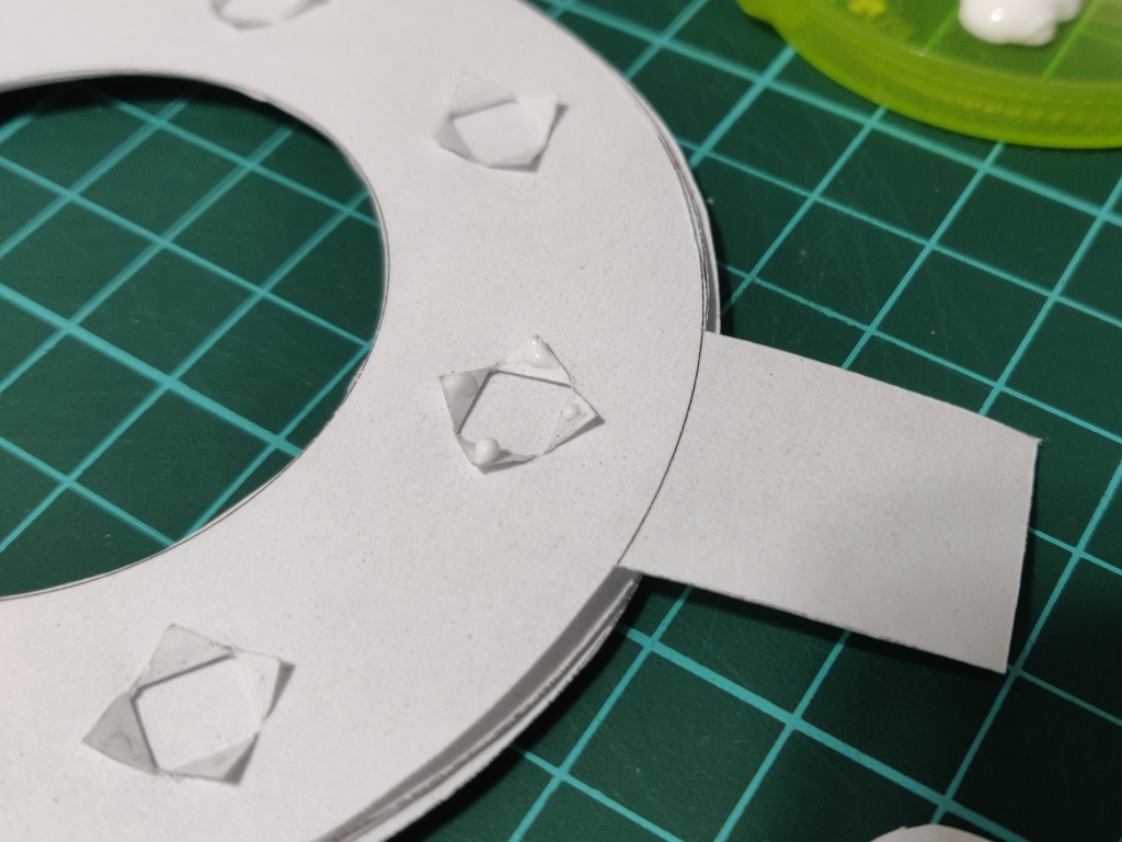
Use a pencil to poke the holes so the triangular leaflets can bend back on themselves around the edge. Make sure they bend in the directions shown in the image.
Assemble the paper iris
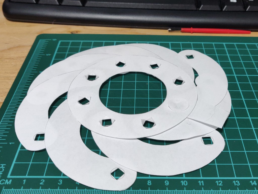
Insert the 'central hole' of the blades into the actuator ring holes one blade at a time, flattening out the leaflets into a circular pattern.
Insert the blades one at a time around the actuator ring, and fan them out.
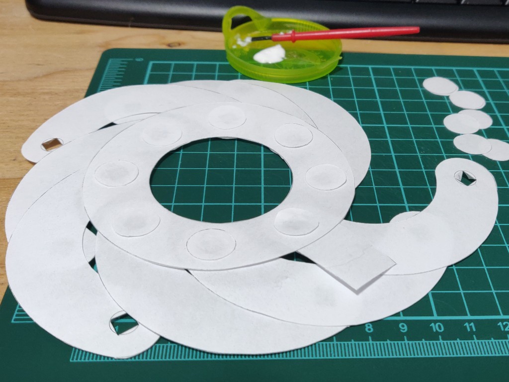
Dab a very small amount of glue on each leaflet, and place a pin cap on top. Press firmly down, but be mindful of excess glue seeping out. You really don't want the glue to get on the moving parts, so double check and rotate the blade a little, just to be sure. The key here is less glue is better, as it's only the leaflets we want to glue.
Next, rotate and stack the blades in a circle. Flip the iris over, place the housing on top and keep in mind which way the handle will rotate - we don't want it to interfere with the tabs when we fold them over.
Glue on the pin caps for the slots. Use a piece of scrap paper to insert between the blade you are gluing and the next. This will prevent any glue seeping between the blades and accidentally gluing them together.
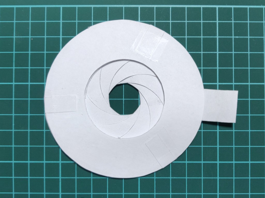
Double check the iris works correctly, then place the lid on top, fold over the 3 tabs over the body and tape them down.
Gently operate the iris to make sure there are no issues. If there’s any resistance or bending, stop and assess where the cause may be. Don’t be tempted to force it, otherwise you may bend or crumple the parts
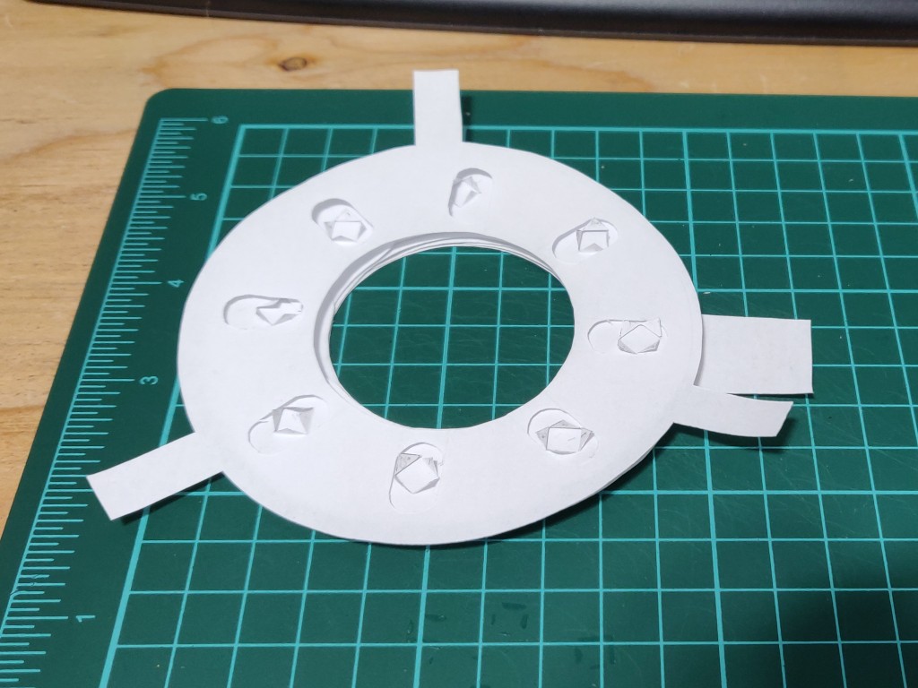
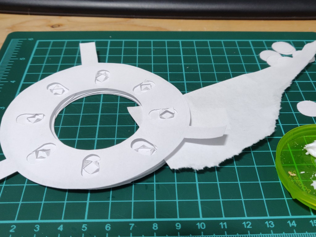
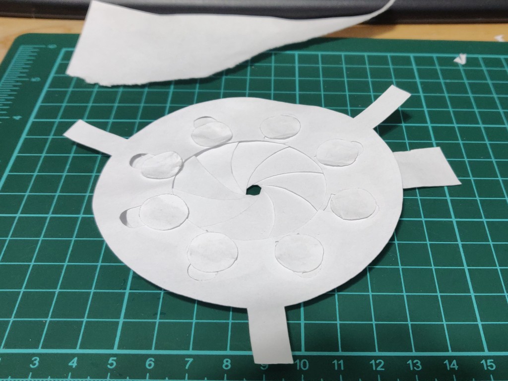
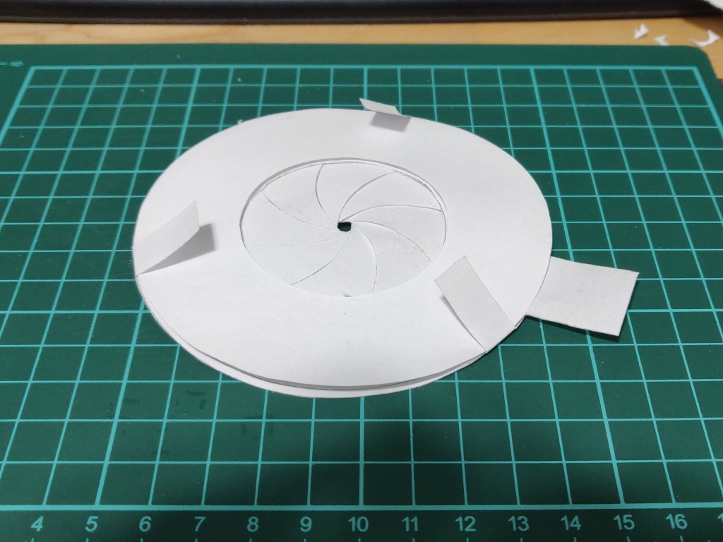
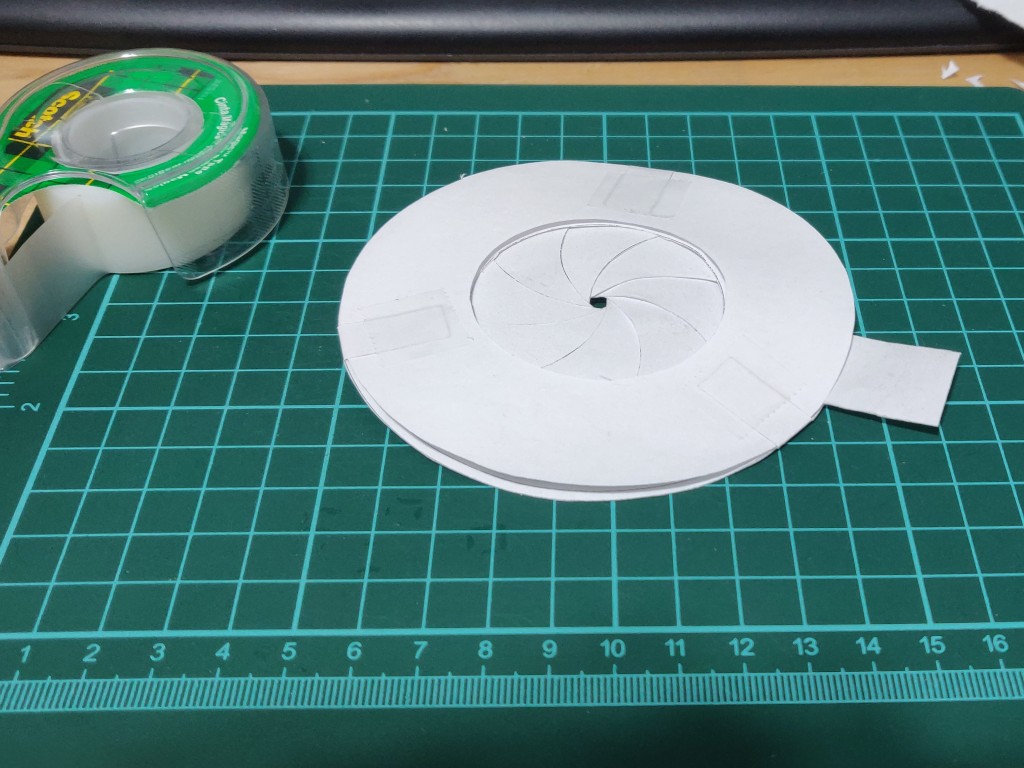
The finished iris diaphragm
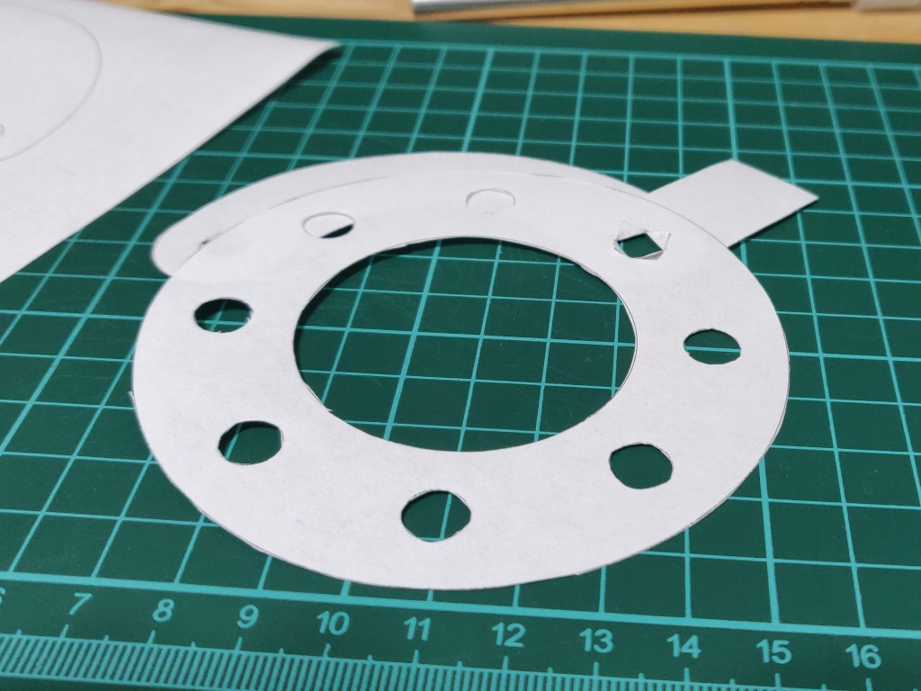
So there you have a paper iris diaphragm, ready to use in your project, or just to play with in your hands!
If you have any suggestions, or are unclear on any of the steps, please do reach out!
Check out some of our other blog posts, such as:
Paper Mechanical Iris Diaphragm